Cornea, an Isometric 3D Graphing Module for Haskell
Table of Contents
| Github | http://github.com/ambuc/cornea |
|---|
While working on the rendering my solution for the Irreversible Pocket Cube, I ended up writing a faux isometric rendering engine which could turn my specific Rubix Cube datastructure into something like an isometric projection of that cube. This my attempt to do it the right way.
The full code lives at ambuc/Cornea.
Mathematics⌗
To quote Wikipedia,
$$ \begin{bmatrix} b_x \\ b_y \\ 0 \end{bmatrix} = \begin{bmatrix} 1 & 0 & 0 \\ 0 & 1 & 0 \\ 0 & 0 & 0 \end{bmatrix} \begin{bmatrix} 1 & 0 & 0 \\ 0 & \cos\alpha & \sin\alpha \\ 0 & -\sin\alpha & \cos\alpha \end{bmatrix} \begin{bmatrix} \cos\beta & 0 & -\sin\beta \\ 0 & 1 & 0 \\ \sin\beta & 0 & \cos\beta \end{bmatrix} \begin{bmatrix} a_x \\ a_y \\ a_z \end{bmatrix} $$
where $\alpha$ and $\beta$ are the pitch and yaw of the camera angle; that is, how far from the equator and meridian in spherical coordinates our viewpoint resides, if the center of the scene is at the origin. This projection matrix works for any 3d point $ \begin{bmatrix} a_x & a_y & a_z \end{bmatrix}^\intercal $ and results in 2d coordinates $ \begin{bmatrix} b_x & b_y & 0 \end{bmatrix}^\intercal $.
metric :: (Float, Float) -> Matrix Float
metric (p, w) = m1 * m2
  where m1 = fromList 3 3 [1, 0, 0, 0, 1, 0, 0, 0, 0]
        m2 = fromList 3 3 [1, 0, 0, 0, cos a, sin a, 0, -sin a, -cos a]
           * fromList 3 3 [cos b, 0, -sin b, 0, 1, 0, sin b, 0, cos b]
          where a = p * pi / 180; b = w * pi * 2 / 360
That’s really all the projection math we need. The name metric is sort of a play on isometric, except the function is extensible and can return a transformation matrix for any viewing angle, not just the default $(35.264,45)$ isometric viewing angle.
Describing the World⌗
data Obj  = Cord [Float] | Edge [[Float]] | Face [[Float]] deriving (Eq, Show)
type Style = ([Primitive] -> Drawing PixelRGBA8 ())
type World = [(Obj, Style)]
Let’s define an Obj object as either
- a single point, a
[Float]list of three floating point numbers describing its $(x,y,z)$ coordinates, or - a list of points describing a line or polyline, or
- a list of points describing a face
Styling the World⌗
We want to be able to style each of these objects. Because I like Graphics.Rasterific, we’ll use their types and define style as a mapping between a [Primitive] and a final Drawing px (). In practice we would use the builtin withTexture (uniformTexture <color>) . fill for a solid fill, or withTexture (uniformTexture <color>) . stroke <width> JoinRound (CapRound, CapRound) for a stroke (used for a line, polyline, or point). In practice it would be nice to provide synonyms in the form of solid k and mark k n.
solid :: Geometry geom => PixelRGBA8 -> geom -> Drawing PixelRGBA8 ()
solid k = withTexture (uniformTexture k) . fill

mark :: Geometry geom => PixelRGBA8 -> Float -> geom -> Drawing PixelRGBA8 ()
mark k n = withTexture (uniformTexture k)
         . stroke n JoinRound (CapRound, CapRound)
Projecting an Object onto a Drawing⌗
Let’s define a convenient type synonym View for our pitch/yaw tuple:
type View = (Float,Float)
and write a proj v <obj> function which can take a coordinate and project it into the plane.
proj :: (Float,Float) -> Obj -> V2 Float
proj v (Cord [x,y,z]) = (\[x,y] -> V2 x y) $ take 2 $ toList
                      $ metric v * Data.Matrix.transpose (fromList 1 3 [y,-z,x])
Great. Now we can plot a coordinate by simply projecting it into the plane. We should be able to plot a line or polyline by projecting each of its coordinates, and a face (or polygon) the same way.
drawFrom :: (Obj, [Primitive] -> t) -> (Float, Float) -> t
(Cord coord, sty) `drawFrom` v = sty $ circle (proj v $ Cord coord) 0.5
(Edge pts  , sty) `drawFrom` v = sty $ polyline $ map (proj v . Cord) pts
(Face pts  , sty) `drawFrom` v = sty $ polygon  $ map (proj v . Cord) pts
Very cool. Let’s construct a sample world and try writing it to a .png.
Writing to .png⌗
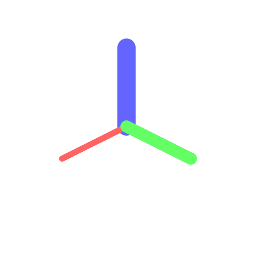
Here’s our calibration world:
calibWorld :: World
calibWorld = [ ( Edge [[0,0,0], [15, 0, 0]] , mark (PixelRGBA8 255 100 100 255) 1)
             , ( Edge [[0,0,0], [ 0,15, 0]] , mark (PixelRGBA8 100 255 100 255) 2)
             , ( Edge [[0,0,0], [ 0, 0,15]] , mark (PixelRGBA8 100 100 255 255) 3)
             ]
Now we need a function which can turn a list of these (Obj,Style) tuples into a single Drawing px () item. We really want to map drawFrom over each of them, and then sequence_ [] the list; we can write that as mapM_ instead, which maps a monad over a list of inputs, discarding the intermediate results along the way.
seenFrom :: World -> (Float,Float) -> Drawing PixelRGBA8 ()
world `seenFrom` v = mapM_ (`drawFrom` v) world
The very final piece of our puzzle is something which takes a Drawing px () and actually turns it into an Image px, which can be written to .png with Rasterific’s writePng.
We’ll need to supply render with a width/height/scale
render :: Int -> Int -> Float -> Drawing PixelRGBA8 () -> Image PixelRGBA8
render x y s d = renderDrawing x y (PixelRGBA8 255 255 255 255)
             $ withTransformation ( translate (V2 (fromIntegral x / 2)
                                                  (fromIntegral y / 2)
                                              ) <> scale s s
                                  ) d
Great. Let’s write this Drawing px () out to an Image px () and eventually to a file IO ().
main = writePng "canvas.png" $ render 500 500 12 $ calibWorld `seenFrom` (35,45)
That’s super! Let’s try something more complicated: define myWorld to be a bunch of intersecting squares along the x-y and y-z planes:
myWorld :: World
myWorld = [ ( Face [[0,0,0], [0, 10,0], [ 10, 10,0], [ 10,0,0] ] , solid $ PixelRGBA8 255 100 0 255)
          , ( Face [[0,0,0], [0,-10,0], [ 10,-10,0], [ 10,0,0] ] , solid $ PixelRGBA8 255 120 0 255)
          , ( Face [[0,0,0], [0,-10,0], [-10,-10,0], [-10,0,0] ] , solid $ PixelRGBA8 255 140 0 255)
          , ( Face [[0,0,0], [0, 10,0], [-10, 10,0], [-10,0,0] ] , solid $ PixelRGBA8 255 160 0 255)
          , ( Face [[0,0,0], [ 10,0,0], [ 10,0, 10], [0,0, 10] ] , solid $ PixelRGBA8 255 180 0 255)
          , ( Face [[0,0,0], [-10,0,0], [-10,0, 10], [0,0, 10] ] , solid $ PixelRGBA8 255 200 0 255)
          , ( Face [[0,0,0], [-10,0,0], [-10,0,-10], [0,0,-10] ] , solid $ PixelRGBA8 255 220 0 255)
          , ( Face [[0,0,0], [ 10,0,0], [ 10,0,-10], [0,0,-10] ] , solid $ PixelRGBA8 255 240 0 255)
          ]
And render it as before:
main = writePng "canvas.png" $ render 500 500 12
      $ (calibWorld++myWorld) `seenFrom` (35,45)

Uh-oh. We’re running into the visibility problem, wherein we don’t know which order to render the faces in so that the things nearer the camera would be visible over the things farther from the camera.
The Visibility Problem⌗
There are a bunch of ways to solve this problem, but I ended up computing a vector from the origin to the centroid of each object, defining a vector from the origin to the position of the camera, and ranking the objects by the scalar projection of each object’s centroid-vector onto the camera-vector.
scalarProject u v = dot v (unit u)
  where dot a b = sum $ zipWith (*) a b
        unit n  = map (/ norm n) n
        norm    = sqrt . sum . map (^2)

avgPts :: [[Float]] -> [Float]
avgPts = map (\xs -> realToFrac (sum xs) / genericLength xs)
       . Data.List.transpose

centroid :: Obj -> [Float]
centroid (Cord coord) = avgPts [coord]
centroid (Edge pts  ) = avgPts pts
centroid (Face pts  ) = avgPts pts

closeness :: (Float,Float) -> [Float] -> Float
closeness (p,w) [x, y, z] = scalarProject (toBaseline p w) [x,y,z]
  where toBaseline :: Float -> Float -> [Float] -- pitch, yaw in degrees
        toBaseline p w = [cos theta * sin phi, sin theta * sin phi, cos phi]
          where theta = w * c; phi = (90-p) * c; c = pi / 180;
Now, instead of just mapM_ (`drawFrom` v) world we can write:
seenFrom :: World -> (Float,Float) -> Drawing PixelRGBA8 ()
world `seenFrom` v = mapM_ (`drawFrom` v)
                   $ sortBy (comparing $ closeness v . centroid . fst) world
Which uses a Data.List builtin sortBy (comparing <comparison_fn>) list to reorder a list according a custom comparison_fn. You could write one like (\a b -> if a > b then a else b), or we could use comparing to rank by an implicit function of each item.
In this case, that implicit function is closeness v . centroid . fst, which takes each (Obj, Style) tuple, extracts the Obj, finds its centroid, and finds the closeness by calculating the scalar product of that centroid-origin vector with the viewpoint-origin vector.
This gets us something a little more reasonable:

Animation⌗
This is pretty cool, but what if we want to animate our world?
Let’s define a series of pitches and yaws to make a cool wobbling sweep around our world. Again, mapM_ lets us map our writePng function over a list of 3-tuples containing the pitch, yaw, and frame number. We can write them out to /tmp/canvas*.png…
pitches = ( map (\x -> 20 * (sin (x * pi / 12) + 1.5)) [0,1..] )
yaws    = [0,5..355]
main = do
  mapM_ (\(p,w,i) -> writePng ("/tmp/canvas" ++ show i ++ ".png")
                 $ render 500 500 $ (calibWorld++myWorld) `seenFrom` (p,w)
        ) $ zip3 pitches yaws [10..]
…and compose them together into a .gif later with convert -loop 0 /tmp/canvas* \<filename\>.

Here’s that contrasted with an animation from before we solved the visibility problem:

Animating with Codec.Picture.Gif⌗
Codec.Picture supports assembling Images into gifs in Haskell, without having to write the frames out to a file and assembling them with convert. It’s a lot slower, though. I’ll present it here just out of interest, but in practice I found it anywhere from 8x-10x slower.
import Codec.Picture
import Codec.Picture.Gif
import Codec.Picture.Types
import Cornea -- this is our module! If you check out the repo
              -- at the very top of the page, you can see how we wrap it into
              -- an importable module.

-- same calibWorld and myWorld as above

options :: PaletteOptions
options = PaletteOptions { paletteCreationMethod=MedianMeanCut, enableImageDithering=True, paletteColorCount=256 }

main = head $ rights
     $ [ writeGifImages "animation.gif" LoopingForever
     $ map ( (\(i,p) -> (p,2,i)) --arbitrary framerate
           . (\(p,w) -> palettize options
                      $ dropAlphaLayer
                      $ render 500 500 12 $ (calibWorld++myWorld) `seenFrom` (p,w)
             )
           ) $ zip ( map (\x -> 20 * (sin (x * pi / 120) + 1.5)) [0,1..] )
                   [0,1..359]
     ]

This took ~3min and I see a bit of flickering – probably because the command-line convert utility understands color and framerate better than I do.
Conclusions⌗
This is a neat little library, just powerful enough to handle the matrix multiplication necessary to take a scene depicted in raw coordinates and render it in a useful way. I have no idea what its performance will be like for a larger scene, but I’ll continue to use it in the future and we’ll see what sorts of optimizations can be made.
I’ve put it on Github here: ambuc/cornea in the hopes that someone else might get a kick out of it.