Partial Mechanical Design of a Pantograph
Table of Contents
| App | http://jbuckland.com/pantograph |
|---|---|
| Github | http://github.com/ambuc/pantograph |
I was inspired by the above video (depicting a set of record players in control of a pantograph) to derive a closed-form solution for the vector position of the pen in terms of the angles of rotation for each of the arms

Derivations⌗
Derivation of nodes $A$, $B$, $P$, $Q$, and $M$⌗
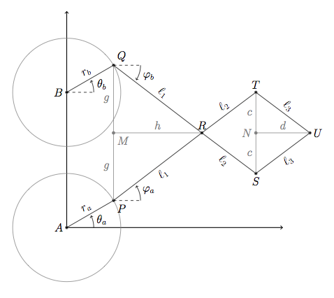
For our pantograph assembly, we define the centers of two circles $A$ and $B$, each with a radius $r_a$ and $r_b$, respectively. The current positions of nodes $P$ and $Q$ are determined by angles $\theta_a$ and $\theta_b$.
Taking the position of $A$ as the origin, we can find
$$ \vec{A} = \Big(0,\ 0\Big) $$
$$ \vec{B} = \Big(0,\ (r_a + d + r_b)\Big) $$
$$ \vec{P} = \vec{A} + \Big( r_a\ \angle\ \theta_a \Big) $$
$$ \vec{Q} = \vec{B} + \Big( r_b\ \angle\ \theta_b \Big) $$
$$ \vec{M} = \frac{1}{2}\left( \vec{P} + \vec{Q}\right) = \Big( \tfrac{1}{2}(P_x + Q_x), \tfrac{1}{2}(P_y + Q_y) \Big)$$
Derivation of node $R$⌗
Attached to the points $P$, $Q$ are two rigid bodies of length $\ell_1$, which meet at variable point $R$. By finding the midpoint $M$ between $P$ and $Q$, we can find the right triangle $\triangle PMR$. From the definition of slope, we find $\overline{PQ}$ to be $$m_{\overline{PQ}} = \dfrac{Q_y - P_y}{Q_x - P_x}$$
Because $\overline{MR} \perp \overline{PQ}$, we can find the slope of the line $\overline{MR}$ to be
$$ m_{\overline{MR}} = \left(m_{\overline{PQ}}\right)^{-1} $$
In addition, we can construct the right triangle $\triangle PMR$ with known side lengths $a$ and $g$, where
$$g = \tfrac{1}{2}|\overline{PQ}| = \tfrac{1}{2}{\sqrt{(Q_x - P_x)^2 + (Q_y - P_y)^2}}$$
Thus, $h = \sqrt{(\ell_1)^2 - g^2}$. This allows us to find
$$\vec{R} = \vec{M} + \left( h\ \angle\ \tan^{-1}\left(m_{\overline{MR}}\right) \right)$$
$$\vec{R} = \vec{M} + \left( \sqrt{a^2 - g^2}\ \angle\ \tan^{-1}\left( \dfrac{-1}{m_{\overline{PQ}}} \right) \right) $$
Derivation of nodes $S$, $T$⌗
We can easily find $\varphi_a$, $\varphi_b$ from the slopes of lines $\overline{PR}$ and $\overline{QR}$, respectively.
$$ \varphi_a = \tan^{-1}\left( \dfrac{R_y - P_y}{R_x - P_x} \right) $$
$$ \varphi_b = \tan^{-1}\left( \dfrac{R_y - Q_y}{R_x - Q_x} \right )$$
We can then write nodes $S$ and $T$ as $$\vec{S} = \vec{R} + \left( \ell_2\ \angle\ \varphi_b\right) $$ $$ \vec{T} = \vec{R} + \left( \ell_2\ \angle\ \varphi_a\right)$$
Derivation of node $U$⌗
It is trivial to present a construction of triangle $\triangle TUS$ that directly mirrors that of triangle $\triangle QRP$. We find
$$\vec{N} = \frac{1}{2}\left(\vec{S} + \vec{T}\right) $$
$$ d = \sqrt{(\ell_3)^2 - c^2} $$
$$ m_{\overline{NU}} = \dfrac{-1}{m_{\overline{ST}}} = -\dfrac{T_x - S_x}{T_y - S_y}$$
Thus, we can write node $U$ as $$\vec{U} = \vec{N} + \left(d\ \angle\ \tan^{-1}\left( m_{\overline{NU}} \right)\right)$$
Distressingly, this appears to be a function that cannot be resolved into a one-to-one mapping from the vector space $(\phi_a, \phi_b)$ onto the $(x,y)$ coordinate system of the pen by any conventional means: that is, for each $(x,y)$ on the pad, there are two or three sets of $(\phi_a, \phi_b)$ positions that could achieve that position.
At a loss with the tools of continuous mathematics, I turned to discrete simulations: a set of three processing.js simulations illustrating what turned out to be a very complex space.
Demos⌗
- Demo $\alpha$: Mouse-driven geometry demo of pantograph behavior
- Demo $\beta$: Mouse-driven geometry demo of point names
- Demo $\delta$: Sample space of points available from an array of rotational values